Chaos Grains
Chaos Grains is a Digital Musical Instrument (DMI) made as part of the Interactive Digital Multimedia Techniques module at Queen Mary University of London. The instrument explores the idea of creating music with chaos. A plasma ball interface is used to control the parameters of a chaos attractor implemented in Max MSP, which is then used as an oscillator to generate sound, effects modulator, and controller for a granular engine.
Performance
Chaos Grains was performed at the C4DM Performance Lab at Queen Mary University of London on Decemeber 9 2025, along with Alex Jolley's ResoBox as a duo.
Demo
This video demonstrates Chaos Grains' capabilities and how different hand movements control the chaos attractor.
Context, Concept and Aims
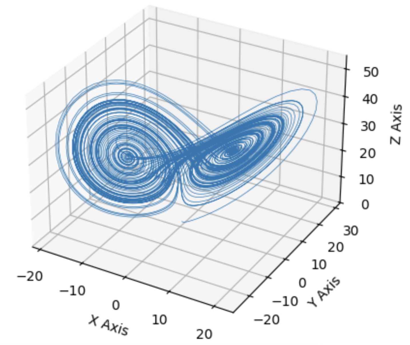
At the heart of the instrument is a chaos attractor. Chaos attractors are a set of states in a chaotic system that the system's trajectory will stay within. The system's overall behaviour remains within a predictable shape, but the exact path taken is unpredictable over the long term. One famous example of a chaos attractor is the Lorenz attractor, developed to understand atmospheric convection, and is also often associated with the idea of the butterfly effect. Apart from modelling physical behaviour, chaos attractors can also be utilized in musical applications by introducing controlled chaos.
In previous research, there has been three main musical applications of chaos attractors. The first being a compositional tool. Bidlack (1992) and Herman (1993) both implemented chaos attractors and mapped each of the vectors to a MIDI parameter such as pitch, note duration and volume. With the use of chaos attractors, they were able to generate complete MIDI compositions. The second way is to use chaos attractors to modulate parameters of an existing sound such as pitch and amplitude (Rizzuti, 2007). More recently, in the book Generating Sound and Organizing Time by Wakefield and Taylor (2022), they used chaos attractors as a way to add controlled variation to sequence timings, giving the sequence a humanized feel. Finally, the last musical application of chaos attractors is sound synthesis. For example, the Chua's attractor was used as an oscillator to generate sound (Choi, 1997) and more recently, chaos attractors were plotted as 3D height maps used in wave terrain synthesis (Franklin, 2024). One common theme throughout the research is that there is no standardized mappings when using chaos attractors in musical applications. It is up to the authors to explore and experiment with different mappings.
The inital aim of this project was to utilize all three of the mentioned musical applications of chaos attractors into one live improvisational instrument. However, due to challenges with mapping when utilized as a compositional tool, it was changed to control a granular engine instead. The final instrument uses the Thomas attractor to synthesize sound, modulate effects, and control a granular engine.
Design Process, Technical and Creative Details
Overview
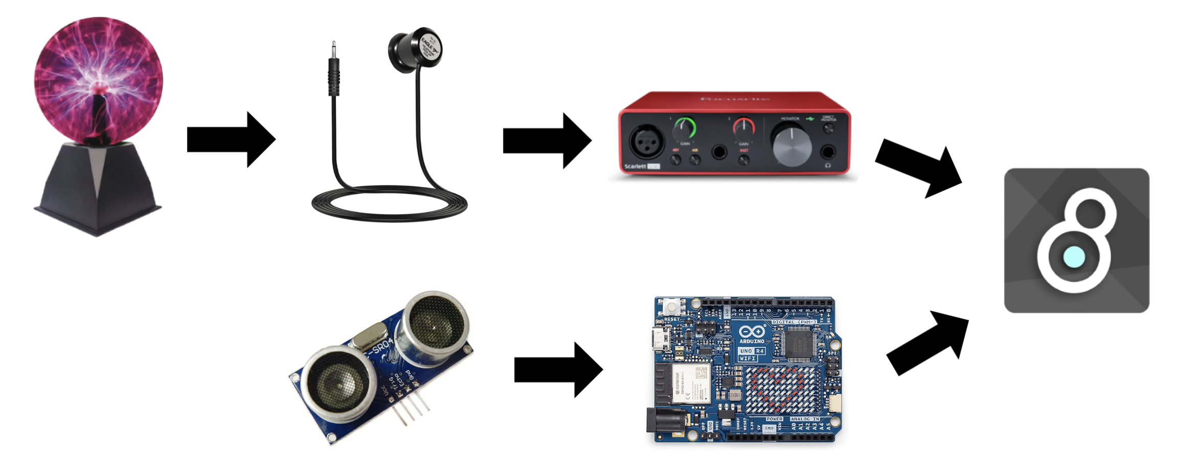
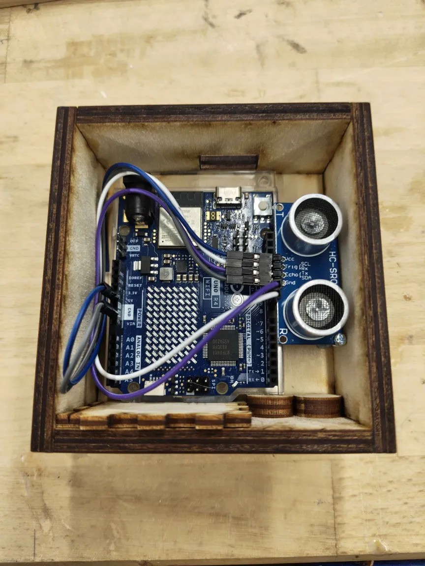
The final instrument was built using Max MSP (sound), Jitter (visuals), Arduino UNO, an ultrasonic sensor, a plasma globe, and a pickup coil. The performer holds the pickup coil in one hand, bringing it closer or farther away from the plasma globe to pick up electromagnetic interference of varying intensities. The detected signal is then sent to Max MSP to control the dt parameter of the chaos attractor. With the other hand, the performer can control the b parameter of the chaos attractor by the height of their hand, and further interact with the plasma ball by tapping or holding it. The height of the hand is detected by the ultrasonic sensor and the distance value is sent to Max MSP through the Arduino. The dt and b parameters are used to control a chaos attractor implemented in Max MSP and Jitter, which controls the sounds and the visuals, with the help of the grainflow package for granular sounds. Early iterations of the physical instrument used an AM radio to pick up electromagnetic interference. However, it was inconsistent, required constant recalibration, and was eventually replaced by the pickup coil. Finally, a wooden box was built to house the Arduino and the ultrasonic sensor. The final code used for the performance can be found here
Sound Synthesis With Chaos Attractor
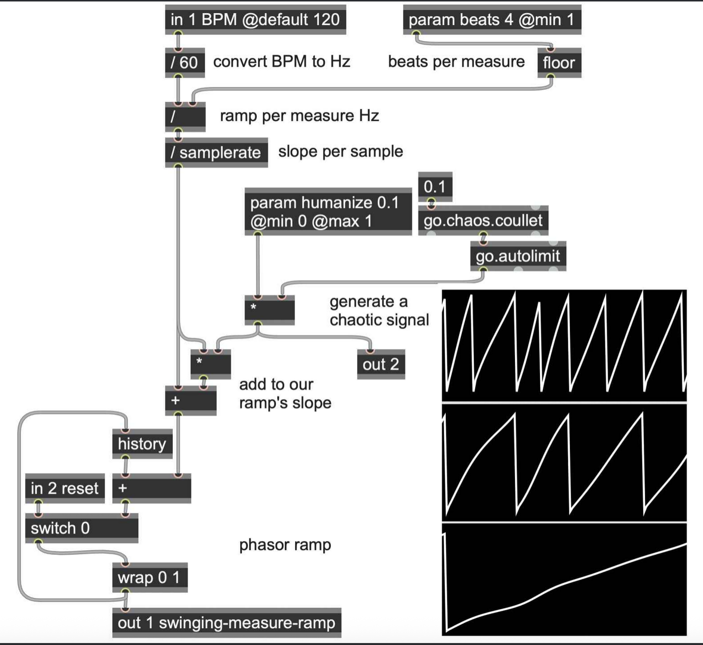
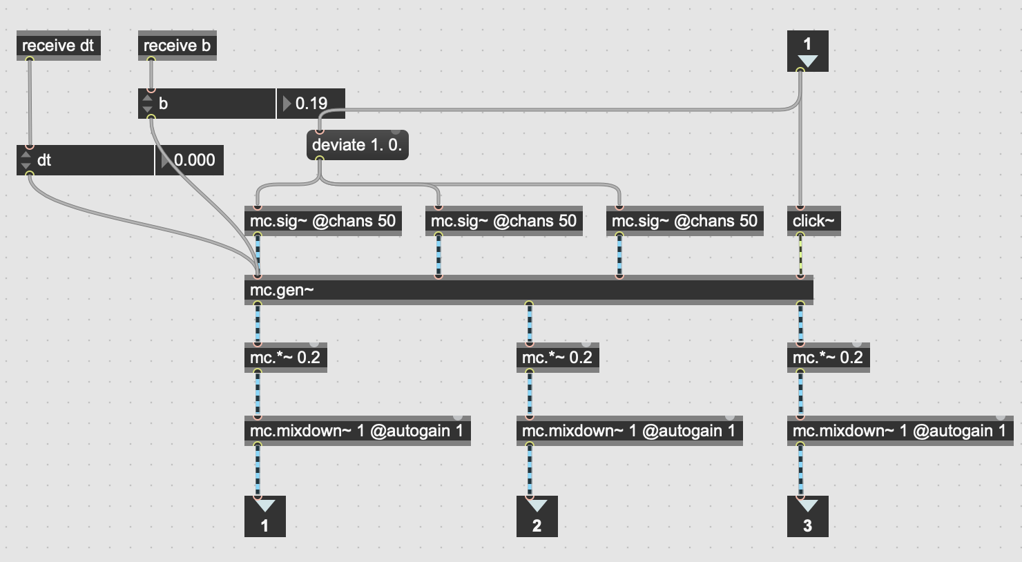
To start off the project, I implemented the Thomas attractor in Max MSP using gen~ following this tutorial by Umut Eldem (2023). The exact differential equations for the Thomas attractor can be found here. This allowed me to generate sound by patching one of the chaos attractor's x, y, or z vectors into the ezdac~ object. The pitch and timbre of the sound can be controlled by adjusting the b and dt parameters in the differential equations. The parameter dt changes how fast the particle in the chaos attractor moves, which changes the pitch, and the parameter b changes the shape of the chaos attractor, which changes both pitch and timbre. I then modified the patch to use mc.gen~ instead of gen~, with 50 channels, to generate a more interesting and textured sound. The resulting oscillator sub patch became the basis for the sound synthesis aspect of the instrument.
Chaos Attractor Visuals
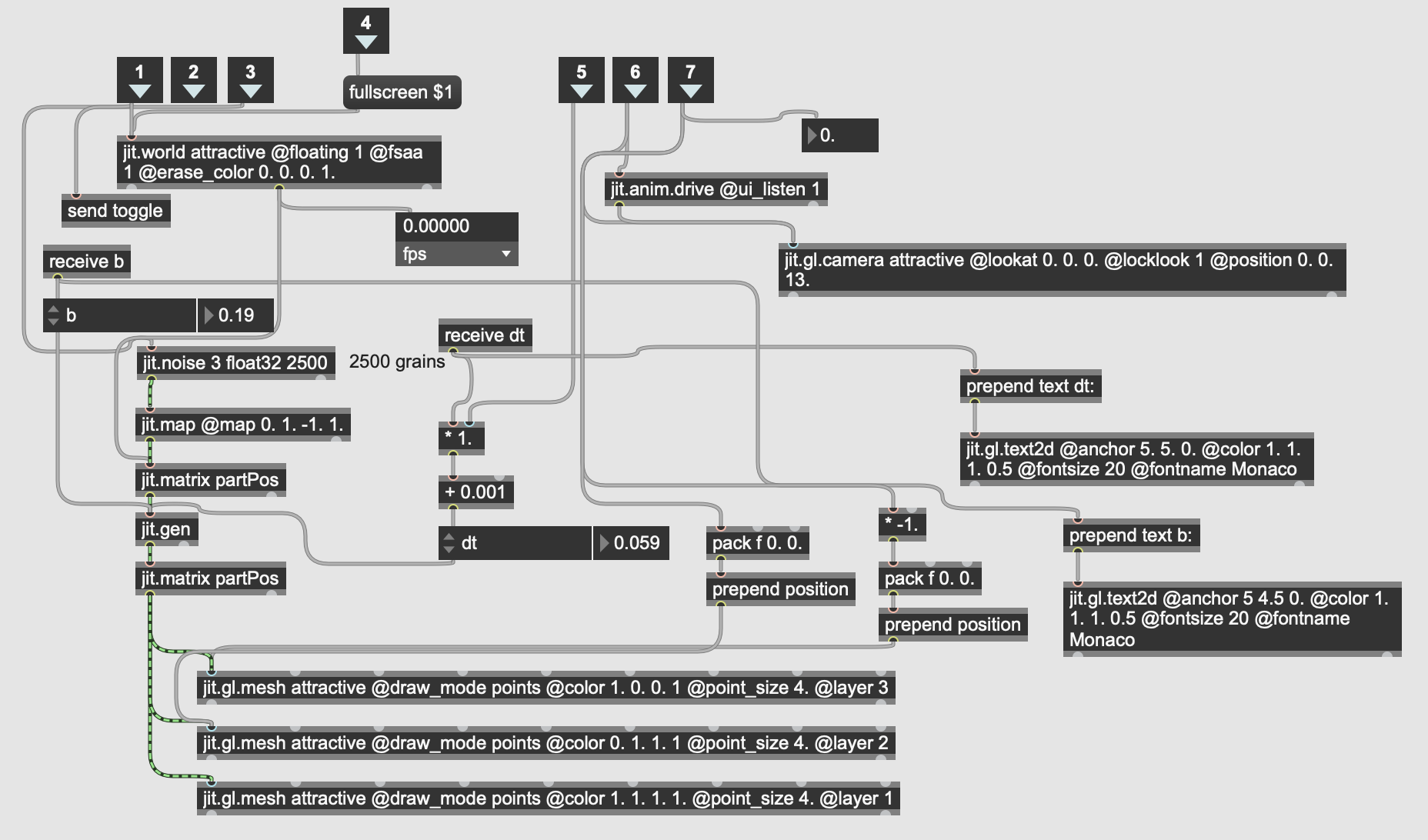
Since the chaos attractor is a crucial part of the instrument, I wanted to visualize it so that I could see how the different parameters are affecting the chaos attractor, and how the shape of the chaos attractor affects the sound. This could be done by patching the vectors to the scope~ object. However, the scope~ object only allows two inputs and therefore was not able to visualize the entire chaos attractor in three dimensions. To solve this issue, I used Jitter, specifically jit.gen, to implement the visuals in three dimensions using the same b and dt parameters that are being fed into the mc.gen~ object. The visuals were implemented with 2500 particles to visualize the full form of the chaos attractor. The visuals you see at the top of this webpage is a faithful recreation of the Jitter visuals implemented in p5js, with the only difference being a reduced number of particles to help with performance on mobile devices.
Modulating Effects With Chaos Attractor
The patch sounded a bit dry so I implemented a feedback loop with two delays, the first being a modulated delay and the second a normal delay. The delay time of the first delay is being modulated by the x vector of the chaos attractor while the delay time of the second delay is set at 100ms. This creates a chorus-ish effect that changes depending on the shape of the attractor, followed by a normal delay. The whole feedback loop has a scaling factor of 0.8.
Hardware Interface
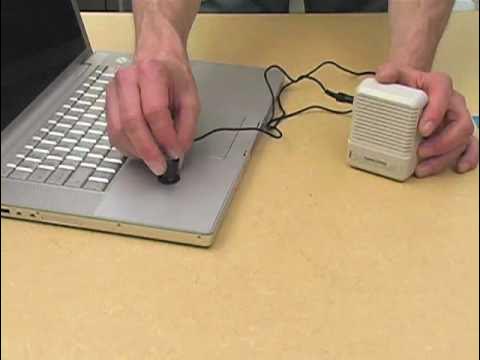
Now that I had an interesting sounding Max patch, I had to come up with a hardware interface to control it. This is when I came across this video by Carl Hudson (2012), where they use a plasma ball to send MIDI data to a Prophet 8 synthesizer. Not only is the plasma globe a chaotic object, which fits with the main idea of the project, it can also be manipulated in a somewhat controllable manner through touch. The aesthetics of the plasma globe also complement the sci-fi futuristic aesthetic of the visuals very well.
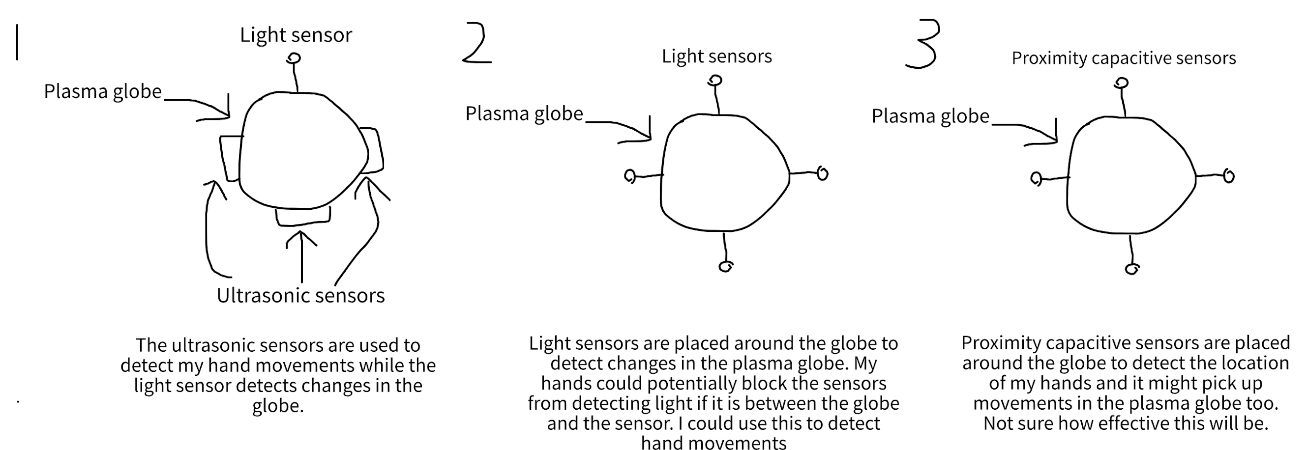
I had a few ideas on how to detect the changes in the plasma ball, as described in the initial sketches above. Hudson (2012) also used light sensors, specifically Light Dependent Resistors (LDR) to detect changes in the light emitted from the plasma globe. However, I opted to detect its electromagnetic (EM) interference instead. This would allow for a relatively consistent instrument regardless of the lighting of the location the instrument is being played in. It will also be able to pick up more intricate changes in the plasma globe compared to the LDR sensor.
First Prototype And Limitations
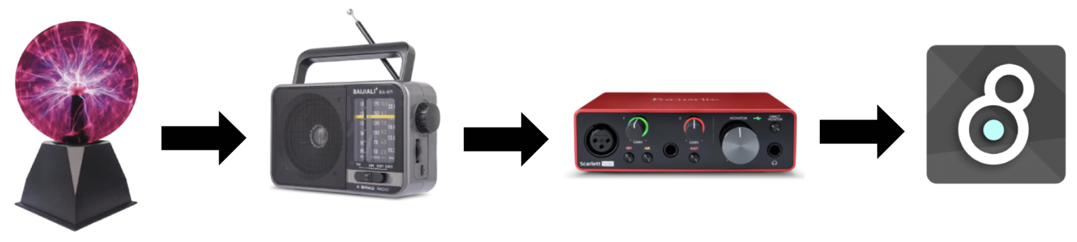
The first prototype uses an AM radio to detect EM interference from the plasma globe, as inspired by this video by Plasma Channel and Keystone Science (2017). The audio output of the AM radio is then sent into a Focusrite Solo and further processed in Max MSP. The Max patch was modified such that the audio signal from the AM radio controls the dt parameter of the chaos attractor. In the prototype, the dry signal from the AM radio is also sent into the feedback loop as added texture.
The prototype had a few short-comings. First, the AM radio had to be set to an empty AM channel in order to pick up the EM interference. However, this changes depending on the location and time of day so you would likely have to recalibrate it every time you use the instrument. Sometimes the AM radio would start picking up a nearby radio channel even after it has been calibrated to an empty channel. Second, it was not as responsive as I wanted it to be. There was a delay between when I touched the globe and when the signal reached the Max patch. It was clear that I needed a different way to pick up EM interference. Third, there was no way to adjust the b parameter of the chaos attractor so the chaos attractor stays at the same shape. I needed to figure out more ways to control the instrument.
Improved Prototype
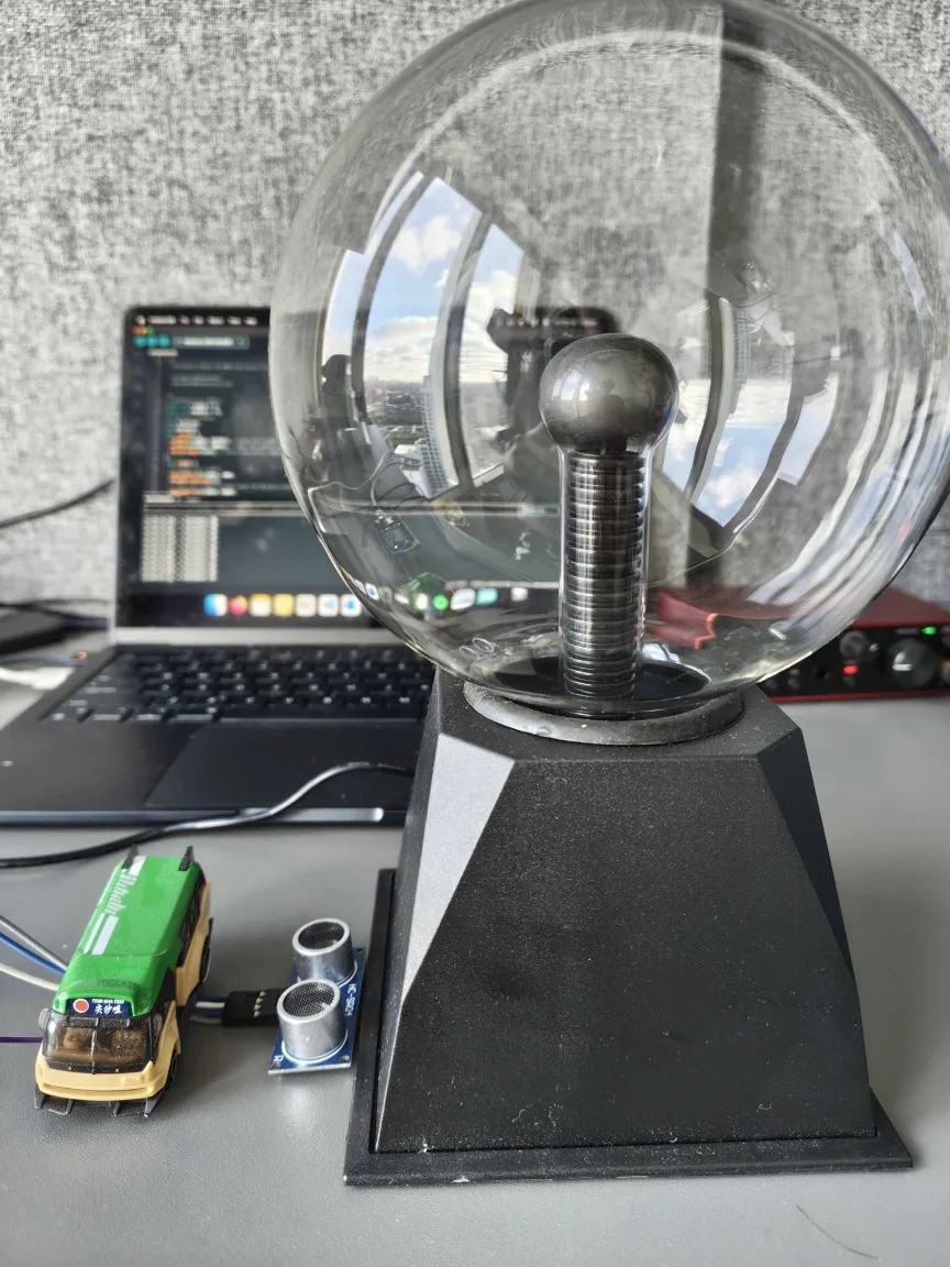
Two main changes were made to solve the issues described above. The AM radio was replaced by a pickup coil to reliably pick up EM vibrations from the plasma globe. This was inspired by "circuit sniffing", introduced in the DIY aesthetics lecture of the IDMT module, where an inductive pickup is used to pick up the sound of EM vibrations. Not only was the pickup coil able to detect when I touch and release the plasma globe, the output signal also got louder as I brought the pickup closer to the plasma globe, and quieter as I moved it away from the plasma globe. This was incorporated into the instrument as a way to add dynamic and expressive playing. The second main change was the added ultrasonic sensor. This allowed me to detect my hand's height when touching the plasma ball and use it as an input to adjust the b parameter of the chaos attractor. The higher my hand is, the higher the b parameter is, and vice versa. The ultrasonic sensor is connected to an Arduino UNO R4 WiFi, which sends serial data to the max patch.
While I contemplated adding more sensors to the instrument, I couldn't help but recall the reading covered in lecture, Dimensionality and Appropriation in Digital Musical Instrument Design (Zappi and McPherson, 2014). The authors gave ten musicians a deliberately constrained musical instrument, either with one degree of freedom (1DoF) or two degrees of freedom (2DoF), and asked them to practice at home and present two performances. The results showed that "the addition of a second degree of freedom had the counterintuitive effect of reducing the exploration of the instrument's affordances" and that "performers in the 1DoF group thought that there were more features left to explore than those in the 2DoF group" (Zappi and McPherson, 2014). As a result, I kept it simple with only one sensor and aimed to search for hidden affordances in my own instrument.
Granular Engine
After rounds of experimentation using the chaos attractor as a compositional tool, I struggled to find a mapping that I was satisfied with. This led me to use the chaos attractor to control a granular engine instead. The visuals also looked like grains so I figured it would be a good fit aesthetically as well. At first, I tried to create my own granular engine in Max MSP with the help of the example granulator patch provided in the IDMT lecture Max: Audio buffers, granular synthesis, OSC. However, I was unable to get it to work properly and ended up using the Max package grainflow instead. My first iteration of the implementation had the x vector of the chaos attractor controlling the position of the grains, the y vector controlling the pitch, and the z vector controlling the density. One issue I noticed is that the shape of the chaos attractor did not affect the output of the granular synth much. Just using one vector of the chaos attractor was not enough to capture the full shape of the chaos attractor. Therefore, I added up all three vectors and used the resulting sum to control the position of the grains instead. This made a noticeable difference and the shape of the chaos attractor now impacts the generated granular sounds. The granular sounds are also sent to the feedback loop mentioned earlier.
Building The Final Physical Instrument
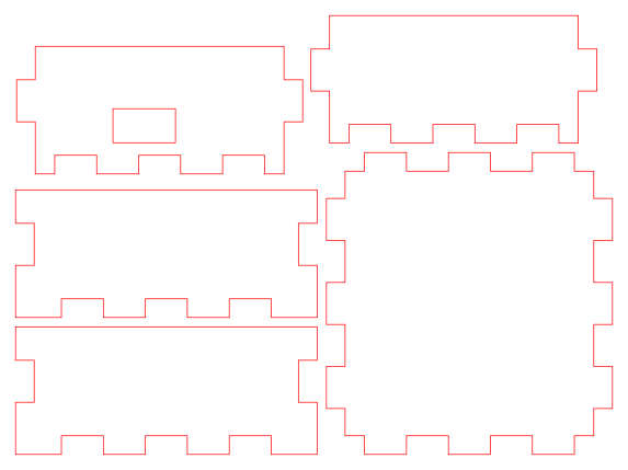
To finish off the hardware, I wanted to build a box to house the Arduino and the ultrasonic sensor. This would allow for a slightly quicker and more consistent setup, as I can instantly line up the sensor by pressing the box against the base of the plasma globe. Previously, I had to position the sensor at just the right spot, otherwise, the sensor would detect the side of the plasma globe instead of my hand. I began by taking measurements of the hardware in the layout I wanted them to be in, then designed the box using Makercase and Affinity. The exact Affinity file used can be found in the extras folder of the GitHub repository. With the help of Geetha Bommireddy, our Materials Lab Technician, I created the panels of the box using laser cutting and glued the panels together with wood glue. As a final touch, I added a sticker I got from ADC25 to the front of the box.
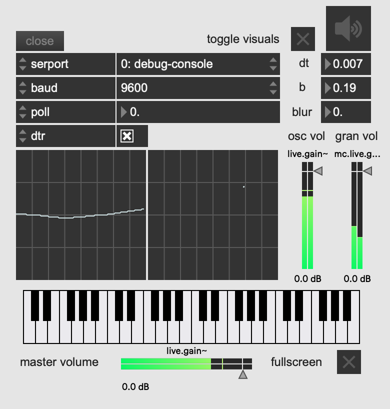
Final Tweaks Before Performance
In the final days of building my instrument, my Max patch has become quite messy. To remove some of the clutter when performing the instrument, I created a presentation mode layout to quickly setup the instrument (set and open ports, toggle visuals, audio and fullscreen visuals), monitor parameters and oscilloscopes, and adjust oscillator, granulator and master volumes. Furthermore, following feedback from lecturer Charalampos Saitis, I added the dt and b parameters of the chaos attractor to the visuals such that it is clearer to the audience what exactly my gestures are controlling.
Due to the collaborative nature of the performance, we wanted Alex's instrument to be able to interact with the visuals as well. Alex suggested implementing an anaglyph 3D effect on the visuals that intensifies as he opens the lid of his ResoBox. We implemented this by sending the distance value from his Max patch to mine through Open Sound Control. In my Max patch, I duplicated the chaos attractor visuals twice, one in red and one in cyan, then used the distance value from Alex's Max patch to scale the horizontal offset of the two duplicate visuals.
Reflection And Future Directions
Overall, I am happy with how Chaos Grains turned out. While it was not able to fully achieve its initial aim, building and designing the instrument has been a great learning experience. A big part of the design process was balancing chaos and control. How do I maintain control and responsiveness in an instrument that is supposed to be chaotic? The tension between chaos and control ultimately shaped the final design of the instrument, one that is responsive to the performer's gestures while still maintaining a certain degree of unpredictability. Another creative skill I developed is knowing when to pivot when an initial idea isn't quite working out. As mentioned by Lecturer Charalampos Saitis in our presentation feedback, having a plan B is important, and my plan B became implementing the granular engine instead of implementing the chaos attractor as a compositional tool. Finally, the main technical skills I learned throughout this project were Max MSP and Jitter. Having no prior experience in Max MSP and Jitter, I spent a lot of time diving into both of them to create the sounds and visuals.
In terms of future directions, there were a lot of ideas I didn't end up implementing due to either budget or time constraints. Given that the chaos attractor was in three dimensions, it seemed like a perfect opportunity to apply it to spatial audio, as suggested by Lecturer Charalampos Saitis. However, this was not explored due to time constraints. Chaos Grains explores specifically the Thomas attractor. However, there are many other chaos attractors out there, some with more adjustable parameters that can open up more possibilities for different sounds and shapes. Another aspect that could be improved upon is being able to control the volumes of the oscillator and the granular engine for a more varied performance. For example, I could start the performance with just the oscillator then slowly introduce the granular sounds throughout the performance. Currently, this can be done in the Max patch but not through the instrument itself.
References
Bidlack, R. (1992). Chaotic Systems as Simple (But Complex) Compositional Algorithms. Computer Music Journal, 16(3), 33–47. https://doi.org/10.2307/3680849Carl Hudson (Director). (2012, October 20). Plasma Ball MIDI controller with Prophet 08 [Video recording]. https://www.youtube.com/watch?v=D7n-BYKB0is
Choi, I. (1997). A chaotic oscillator as a musical signal generator in an interactive performance system. Journal of New Music Research, 26(1), 17–47. https://doi.org/10.1080/09298219708570715
Franklin, A. (2024). Chaotic Systems as 3D Height Maps for Sound Synthesis. 2nd Audiovisual Symposium 2024 December 6, 2024, Dalarna Audiovisual Academy (DAVA), Dalarna University, Falun, Sweden. https://urn.kb.se/resolve?urn=urn:nbn:se:mdh:diva-70386
Hearing Glass, Umut Eldem (Director). (2023, August 4). Chaotic Sounds—Max/MSP Tutorial [Video recording]. https://www.youtube.com/watch?v=EwunJYwxNcs
Plasma Channel (Director). (2017, August 7). DIY Plasma Ball Theremin! ( Ft. Keystone Science) [Video recording]. https://www.youtube.com/watch?v=heCOG1Haobk
Rizzuti, C. (2007, July 11). Mapping Chaotic Dynamical Systems Into Timbre Evolution. 4th Sound and Music Computing Conference (SMC2007). Zenodo. https://doi.org/10.5281/zenodo.849375
siliconluthier (Director). (2010, May 10). Hack of the Month Club -- Project #1: Circuit Sniffing [Video recording]. https://www.youtube.com/watch?v=4T7qkYY7LZM
Zappi, V., & McPherson, A. (2014, June 1). Dimensionality And Appropriation In Digital Musical Instrument Design. https://doi.org/10.5281/ZENODO.1178993